MIL-DTL-17361G(SH)
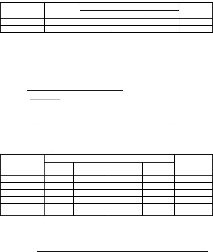
TABLE XIII. Instantaneous timing test (thermal magnetic and electronic trip units) /1.
Actual trip time
Required trip
Applied current
Inst. switch setting /2
time /4
(amps) /3
Left pole
Center pole
Right pole
Min. setting
Intermediate setting
NOTES:
/1 Where applicable, STD and STDPU settings shall be set to the maximum.
/2 Minimum and intermediate (or as close to middle as possible) instantaneous setting available on the circuit
breaker as specified in the individual specification sheets (see 3.1).
/3 Applied current is equal to 3 times the nominal pickup current of the instantaneous setting.
/4 Circuit breakers with thermal magnetic trip units shall trip without intentional delay and shall trip within the
times specified in the applicable specification sheet. Circuit breakers with electronic trip units shall trip without
intentional delay and shall trip in less time than the fastest published time of the lowest STD band (see 3.1).
4.5.10.2 Calibration of circuit breakers with electronic trip unit.
4.5.10.2.1 Long-time delay. Circuit breakers shall be tested in a 50 °C ambient temperature in accordance with
Table XIV (a). Sufficient time between tests shall be allowed for adequate cooling of the circuit breaker. Tests shall
be performed on each pole and then on all poles simultaneously using three-phase power (not three poles in series).
Sufficient time between tests shall be allowed for adequate cooling of the circuit breaker.
4.5.10.2.1.1 Long-time thermal memory (for circuit breakers with electronic trip units only). Circuit breakers
shall be tested for long-time thermal memory in a 50 °C ambient temperature immediately following the highest
applied current level test of the long-time calibration test of 4.5.10.2.1 as shown in Table XIV (a). The thermal
memory tripping time upon the immediate retest shall be less than the tripping time recorded for the previous LTD
tripping event at the highest applied current level.
TABLE XIV (a). Long-time delay and long-time thermal memory testing (electronic trip units).
Actual trip time
Required trip
Current level
All poles
time
applied /1
Left pole
Center pole
Right pole
(3-phase) /3
Long-time thermal
memory test /2
NOTES:
/1 Current levels as specified in individual specification sheets (see 3.1).
/2 In accordance with the test specified in 4.5.10.2.1.1.
/3 Three-phase power, not three poles in series.
4.5.10.2.1.1.1 Example of long-time delay and long-time thermal memory testing (AQB-A252 circuit breaker).
Table XIV (b) shows how an electronic AQB-A252 circuit breaker would be tested for long-time delay and long-
time thermal memory. See AQB-A252 specification sheet to understand how current levels and required trip times
are determined.
28
For Parts Inquires submit RFQ to Parts Hangar, Inc.
© Copyright 2015 Integrated Publishing, Inc.
A Service Disabled Veteran Owned Small Business