MIL-DTL-17361G(SH)
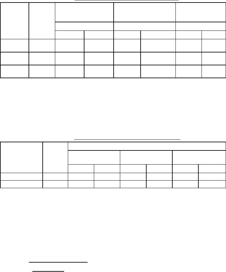
TABLE XVI. Short-time delay trip time testing (electronic trip units).
Right pole (short time
Left pole (short time delay Center pole (short time delay
delay switch set at
Short time
switch set at min.) /4
switch set at intmd) /3 /4
Applied
max.) /4
pickup
current
switch
(amps)
Trip time
Trip time
Trip time
setting /1
Required /2
Actual
Required /2
Actual
Required /2
Actual
3 times
Min. setting
STDPU
Intermediate
3 times
setting
STDPU
3 times
Max. setting
STDPU
NOTES:
/1 Minimum, intermediate (or as close to middle as possible) and maximum STDPU setting available on the circuit
breaker as specified in the individual specification sheets (see 3.1).
/2 Allowable time band as specified in the individual specification sheets (see 3.1) for short-time tripping.
/3 Intermediate (or as close to middle as possible) STD setting available on the circuit breaker as specified in the
individual specification sheets (see 3.1).
/4 Duration of applied current shall be one-half (1/2) cycle greater than the circuit breaker STD setting bandwidth
maximum as specified in the individual specification sheets (see 3.1).
TABLE XVII. Short-time resettable delay testing (electronic trip units).
Trip status
Applied
STDPU switch
Left pole (time delay
Center pole (time delay
Right pole (time delay
current
setting /1
switch set at min.) /5
switch set at intmd.) /4 /5
switch set at max.) /5
(amps) /2
Required
Actual /3
Required
Actual /3
Required
Actual /3
Intermediate setting
No trip
No trip
No trip
Max. setting
No trip
No trip
No trip
NOTES:
/1 Intermediate (or as close to middle as possible) and maximum STDPU setting available on the circuit breaker as
specified in the individual specification sheets (see 3.1).
/2 Applied current level shall be 120% of the nominal short-time delay pickup current.
/3 If the circuit breaker holds, enter "No Trip" or if the circuit breaker trips enter "Trip". After a no-trip event, cycle
the circuit breaker manually from off to on.
/4 Intermediate (or as close to middle as possible) STD setting available on the circuit breaker as specified in the
individual specification sheets (see 3.1).
/5 Duration of applied current shall be one-half (1/2) cycle less than the circuit breaker STD setting bandwidth
minimum as specified in the individual specification sheets (see 3.1).
4.5.10.3 Abbreviated calibration testing.
4.5.10.3.1 Long-time delay. LTD calibration shall be tested in accordance with that of 4.5.10.1.1 for thermal
magnetic trip unit circuit breakers and in accordance with 4.5.10.2.1 for electronic trip unit type circuit breakers.
For calibration testing of thermal magnetic trip unit type circuit breakers after shock (test no. 6 of Table VI) and
after vibration (test no. 9 of Table VI), the following caveats apply for thermal magnetic trip unit type circuit
breakers only:
31
For Parts Inquires submit RFQ to Parts Hangar, Inc.
© Copyright 2015 Integrated Publishing, Inc.
A Service Disabled Veteran Owned Small Business